
Designing IT systems integration using UML
Posted by Marcin Ziemek on 24-09-2022Would you like to learn the method of designing IT systems integration using UML notation? From this text you will learn what UML notation is and how to use it to design IT system integration.
If you want to develop your knowledge of IT systems integration design, check out my book available at: https://integration.marcinziemek.com
What is UML?
When designing and documenting the integration of IT systems, it is worth using popular notations and tools. Notations such as UML or BPMN make it easier to understand the details of the designed integrations. The use of tools such as text document, spreadsheets, confluence, or swagger can help in designing and documenting the integration of IT systems.
In this article I will present what it is and how to use UML notation to design IT systems integration.
Let's start by explaining what UML notation is.
UML (Unified Modeling Language) is a graphical method of modeling information systems. It enables the design of systems using diagrams. The notation consists of graphic elements depicting static and dynamic elements of the designed IT systems.
The most popular diagrams used to design IT systems integration are:- Sequence diagram,
- Component diagram,
- Class diagram,
- Use case diagram,
- Deployment diagram.
Detailed information about UML notation is available on the Object Management Group (OMG) website https://www.omg.org/spec/UML/About-UML/.
Sequence diagram
A sequence diagram is used to show the interaction between actors. It allows to present the order of interactions or the type of interaction (synchronous, asynchronous integration).
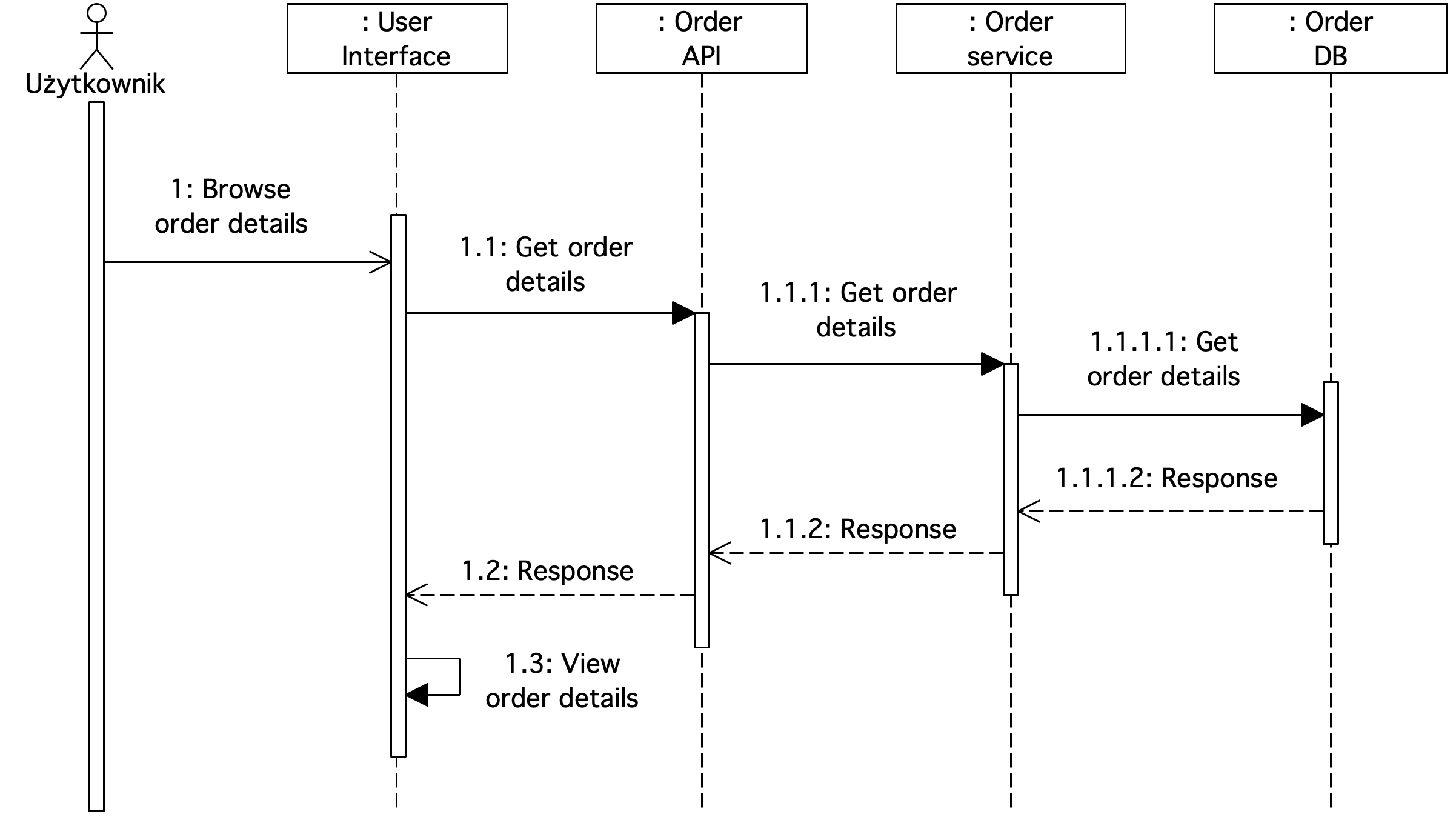
Figure 1. Sequence diagram showing the process of viewing order details
From the sequence diagram we can read the sequence of interactions between actors and the type of interaction. In the above case, the UI calls the function to retrieve order details, which is synchronous.
Component diagram
A component diagram provides a representation of your organization's systems and subsystems and their relationships. Components can represent a system or a part of it. Links are represented by interfaces. The diagram allows you to show a list of interfaces shared or used by the component.
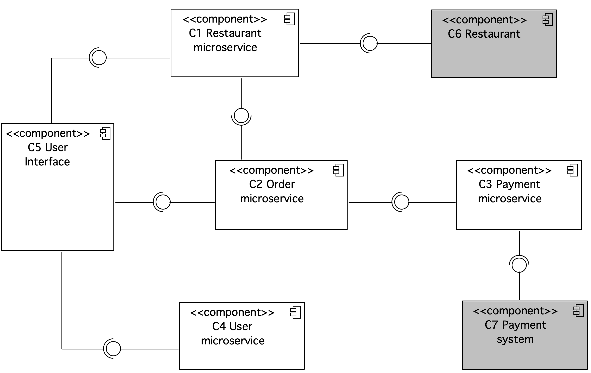
Figure 2. Component diagram showing the application architecture
From the component diagram we can read the connections between the components of the microservices User Interface and Restaurant and between Order and User.
Class diagram
A class diagram is used to represent for solving classes (types) of objects along with the relationships between them. It also allows you to present the attributes (properties) and methods (functions) of classes.
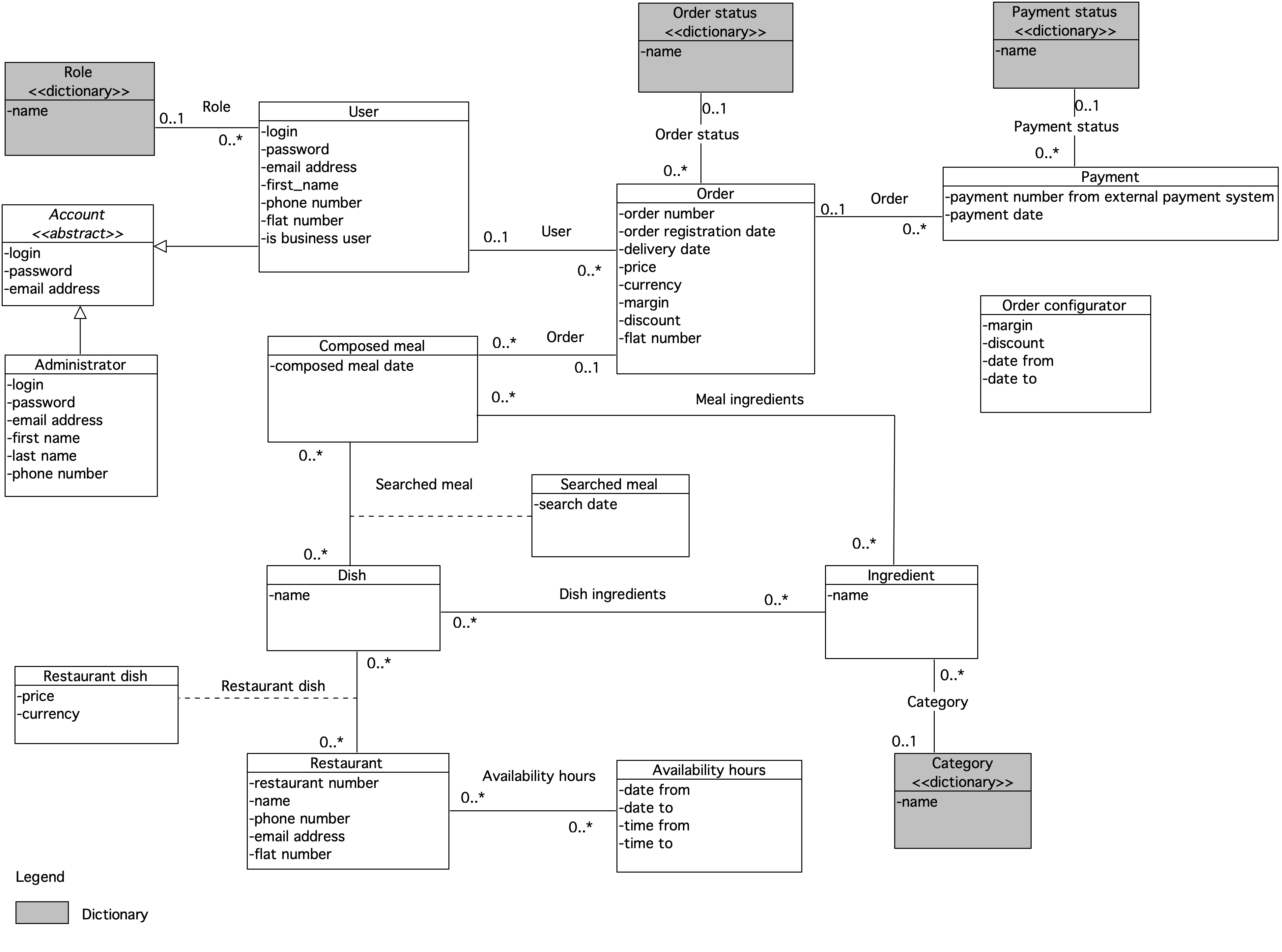
Figure 3. Class diagram showing the solution data model
From the class diagram, we can learn about the main classes of objects in the solution, their attributes, and associations. The diagram above shows the data model for the solution that we will design in the book.
Use case diagram
Use case diagram allows you to show the functions of the system and its surroundings. It contains use cases, actors, and connections between them.
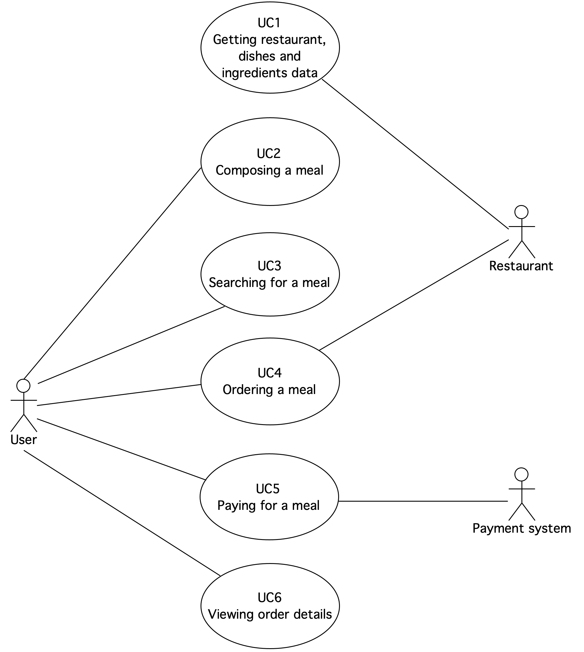
Figure 4. Use case diagram showing the Order domain
From the use case diagram, we can read the functions of the system along with the actors. It also makes it possible to present the relationship between use cases and actors.
Deployment diagram
A deployment diagram is used to show the physical structure of the system, the hardware and software used. It contains nodes, artifacts, and connections between them.
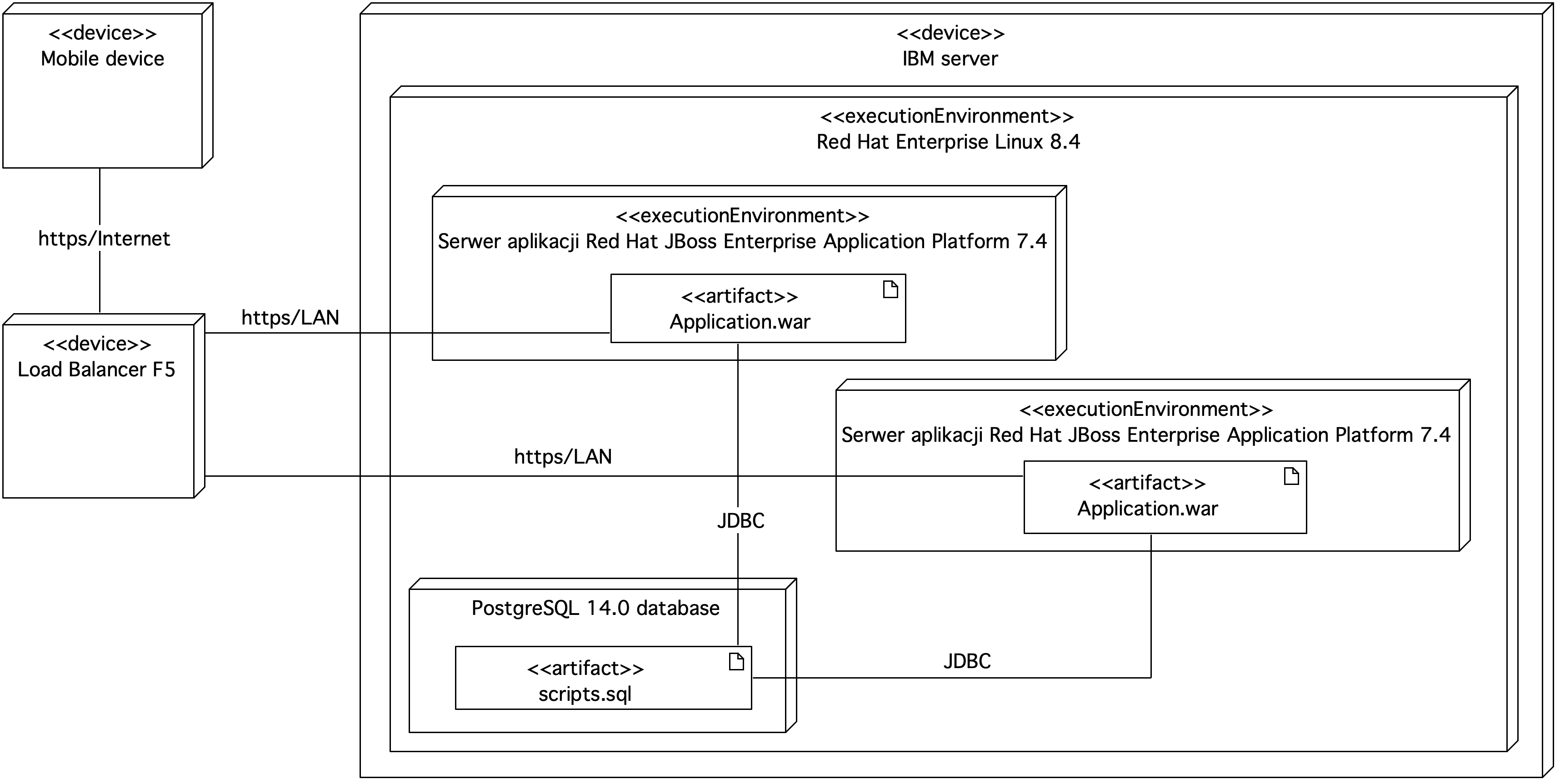
Figure 5. Deployment diagram – sample solution
From the implementation diagram we can read what application servers, operating system, or database we will use. In addition, it also presents artifacts such as application.war installed on the application server.
Thank you for reading the article. If you would like to share your comment with me, write to me at marcin@marcinziemek.com
If you want to develop your knowledge of IT systems integration design, check out my book available at: https://integration.marcinziemek.com